
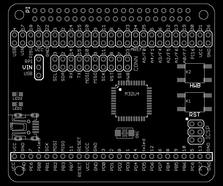
Pinout AVRPi-32U4
The female 2x25 header on the top of the board is connected to the GPIO pins of the Raspberry Pi and some analog pins of the ATmega32U4. The female 1x25 header on the bottom of the board is connected to the pins of the ATmega32U4, and contains all 'digital Arduino' pins.
The board also contains dual row male headers to directly connect suitable pins from the ATmega32U4 to the Raspberry Pi.
RPI HeaderAll of the Raspberry Pi GPIO pins are broken out to this header. For a detailed description of these pins, see: http://elinux.org/RPi_BCM2835_GPIOs 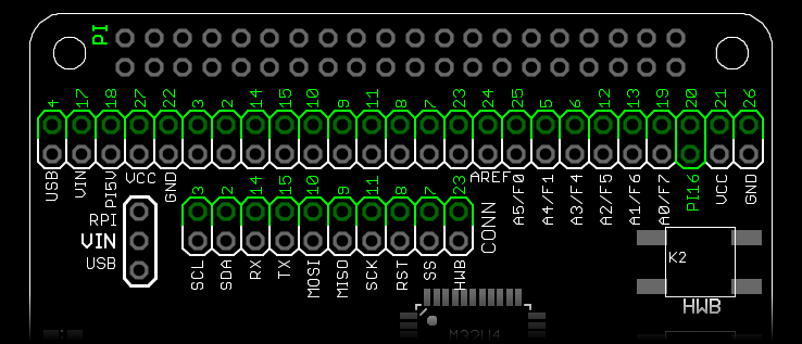 | ||||
| Pin | Type | Pull | Default | Remap |
|---|---|---|---|---|
| GPIO4 | I/O | high | GPIO4 | GPCLK0 |
| GPIO17 | I/O | low | GPIO17 | GPIO_GEN0 |
| GPIO18 | I/O | low | GPIO18 | GPIO_GEN1 |
| GPIO27 | I/O | low | GPIO27 | GPIO_GEN2 |
| GPIO22 | I/O | low | GPIO22 | GPIO_GEN3 |
| SCL.3 | I/O | high | GPIO3 | I2C1_SCL |
| SDA.2 | I/O | high | GPIO2 | I2C1_SDA |
| TX.14 | I/O | low | GPIO14 | USART_TXD |
| RX.15 | I/O | low | GPIO15 | USART_RXD |
| MOSI.10 | I/O | low | GPIO10 | SPI0_MOSI |
| MISO.9 | I/O | low | GPIO9 | SPI0_MISO |
| SCK.11 | I/O | low | GPIO11 | SPI0_SCK |
| CE0.8 | I/O | high | GPIO8 | SPI0_CE0 |
| CE1.7 | I/O | high | GPIO7 | SPI0_CE1 |
| GPIO23 | I/O | low | GPIO23 | GPIO_GEN4 |
| GPIO24 | I/O | low | GPIO24 | GPIO_GEN5 |
| GPIO25 | I/O | low | GPIO25 | GPIO_GEN6 |
| GPIO5 | I/O | high | GPIO5 | CAM_CLK |
| GPIO6 | I/O | high | GPIO6 | LAN_RUN |
| GPIO12 | I/O | low | GPIO12 | |
| GPIO13 | I/O | low | GPIO13 | |
| GPIO19 | I/O | low | GPIO19 | |
| GPIO20 | I/O | low | GPIO20 | |
| GPIO21 | I/O | low | GPIO21 | CAM_GPIO |
| GPIO26 | I/O | low | GPIO26 | |
| GPIO16 | I/O | low | GPIO16 | STATUS_LED |
AVR1 Header (ATmega32U4)Some of the ATmega32U4 GPIO pins are broken out on this header. Please note that some of the pins may also be connected to Raspberry Pi GPIO pins, depending on what jumpers are on the CONN header. There are also power related pins on this header. Please note that the PI5V pin on this header is powered from the Raspberry Pi. If you're backpowering 5V to the Raspberry Pi through the PI5V pin, please take the necessary precautions.  | ||||
| Pin | Type | Arduino | Default | Remap |
| USB | PWR | VUSB (5V) | 5V0 Power from USB | output only |
| VIN | PWR | - | External (PWR) | 5V0 from RPI or USB |
| PI5V | PWR | - | 5V0 from RPI | output only |
| VCC | PWR | - | VCC (3V3) | Powers the board |
| GND | PWR | - | GND | |
| PD0 | I/O | 3 | GPIO (SCL) | OC0B/SCL/INT0 |
| PD1 | I/O | 2 | GPIO (SDA) | SDA/INT1 |
| PD2 | I/O | 0 | GPIO (RX) | RXD1/INT2 |
| PD3 | I/O | 1 | GPIO (TX) | TXD1/INT3 |
| PB2 | I/O | MOSI | GPIO | PDI/PCINT2/MOSI |
| PB3 | I/O | MISO | GPIO | PDI/PCINT3/MISO |
| PB1 | I/O | SCK | GPIO | PCINT1/SCLK |
| RST | I/O | RESET | RESET | RESET |
| PB0 | I/O | rxled | GPIO | SS/PCINT0 |
| PE2 | I/O | - | GPIO | HWB |
| AREF | REF | AREF | AREF | |
| PF0 | I/O | A5 | GPIO | ADC0 |
| PF1 | I/O | A4 | GPIO | ADC1 |
| PF4 | I/O | A3 | GPIO | ADC4/TCK |
| PF5 | I/O | A2 | GPIO | ADC5/TMS |
| PF6 | I/O | A1 | GPIO | ADC6/TDO |
| PF7 | I/O | A0 | GPIO | ADC7/TDI |
| VCC | PWR | - | VCC (3V3) | Powers the board |
| GND | PWR | - | GND | |
VIN HeaderThe ATmega32U4 on the board is powered by the VCC pin. Put a jumper on either RPI/VIN or USB/VIN, depending on what source you want to use for the 3V3 voltage regulator to power VCC. 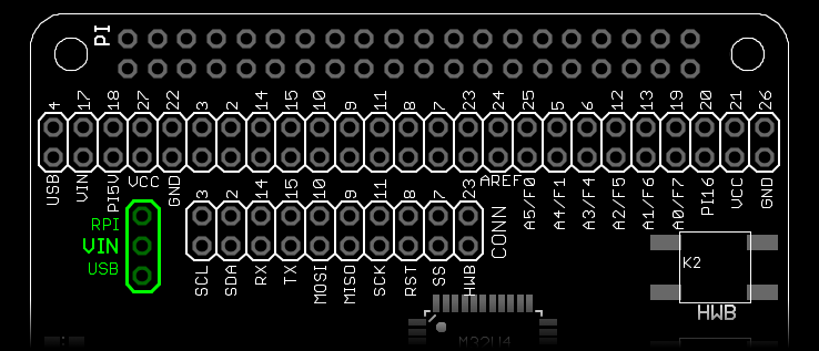 | ||||
| Pin | Type | Startup | Default | With Jumper |
| RPI | PWR | - | 5V0 from RPI | output only |
| VIN | PWR | - | External (PWR) | 5V0 from RPI or USB |
| USB | PWR | VUSB (5V) | 5V0 Power from USB | output only |
CONN HeaderOn the CONN header you can make direct connections from the ATmega32U4 to the RPI (USART, I2C, SPI, RST, HWB) using jumpers. To program the ATmega32U4, put jumpers on 'MOSI-10', 'MISO-9', 'SCK-11' and 'RST-8'. After programming is done you can do with the pins as you please (see RPI and AVR header). To be able to communicate with the ATmega32U4 in 'minicom' or 'screen', put a jumper on 'RX-14' and 'TX-15'. For faster communication than UART, jumper the appropriate pins and use the ATmega32U4 as an I2C or SPI slave (the Raspberry Pi can only be master). 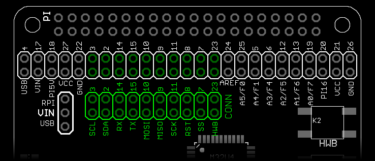 | ||||
| Pin | Type | Function | With Jumper | Info |
| SCL-IO3 | I/O | I2C | Connects ATmega32U4 SCL (PD0) to RPI SCL (GPIO3) | |
| SDA-IO2 | I/O | I2C | Connects ATmega32U4 SDA (PD1) to RPI SDA (GPIO2) | |
| RX-IO14 | I/O | UART | Connects ATmega32U4 RX (PD2) to RPI TX (GPIO14) | |
| TX-IO15 | I/O | UART | Connects ATmega32U4 TX (PD3) to RPI RX (GPIO15) | |
| MOSI-IO10 | I/O | SPI | Connects ATmega32U4 MOSI (PB2) to RPI MOSI (GPIO10) | jumper for programming |
| MISO-IO9 | I/O | SPI | Connects ATmega32U4 MISO (PB3) to RPI MISO (GPIO9) | jumper for programming |
| SCK-IO11 | I/O | SPI | Connects ATmega32U4 SCK (PB1) to RPI SCK (GPIO11) | jumper for programming |
| RST-IO8 | I/O | SPI | Connects ATmega32U4 RST (RST) to RPI CE0 (GPIO8) | jumper for programming |
| SS-IO7 | I/O | SPI | Connects ATmega32U4 SS (PB0) to RPI CE1 (GPIO7) | |
| HWB-IO23 | I/O | HWB | Connects ATmega32U4 HWB (PE2) to RPI GPIO23 | |
ICSP Header (ATmega32U4)On the ICSP header you can connect an external programmer to program the chip. Do not connect a programmer when the AVRPi board is still on the Raspberry Pi! At least remove all the jumpers from the CONN header first, or (better) remove the board completely from the Pi. Whatever you do, don't put jumpers on these header. Things won't break, but they won't work either. 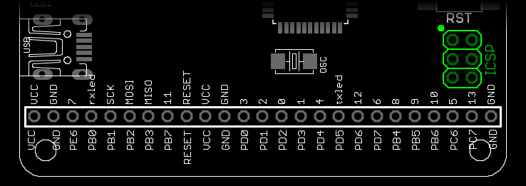 | ||||
| Pin | Type | Arduino | Default | Remap |
| PB3 | I/O | MISO | GPIO | PDI/PCINT3/MISO |
| VCC | PWR | - | VCC (3V3) | Powers the board |
| PB1 | I/O | SCK | GPIO | PCINT1/SCLK |
| PB2 | I/O | MOSI | GPIO | PDI/PCINT2/MOSI |
| RST | I/O | RESET | RESET | RESET |
| GND | PWR | - | GND | |
AVR2 Header (ATmega32U4)All of the ATmega32U4 GPIO pins are broken out on this header. Please note that some of the pins may also be connected to Raspberry Pi GPIO pins, depending on what jumpers are on the CONN header. 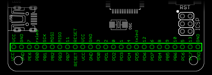 | ||||
| Pin | Type | Arduino | Default | Remap |
| VCC | PWR | - | VCC (3V3) | Powers the board |
| GND | PWR | - | GND | |
| PE6 | I/O | 7 | GPIO | INT6/AIN0 |
| PB0 | I/O | rxled | GPIO | SS/PCINT0 |
| PB1 | I/O | SCK | GPIO | PCINT1/SCLK |
| PB2 | I/O | MOSI | GPIO | PDI/PCINT2/MOSI |
| PB3 | I/O | MISO | GPIO | PDI/PCINT3/MISO |
| PB7 | I/O | 11 | GPIO | PCINT7/OC0A/OC1C/RTS |
| RST | I/O | RESET | RESET | RESET |
| VCC | PWR | - | VCC (3V3) | Powers the board |
| GND | PWR | - | GND | |
| PD0 | I/O | 3 | GPIO (SCL) | OC0B/SCL/INT0 |
| PD1 | I/O | 2 | GPIO (SDA) | SDA/INT1 |
| PD2 | I/O | 0 | GPIO (RX) | RXD1/INT2 |
| PD3 | I/O | 1 | GPIO (TX) | TXD1/INT3 |
| PD4 | I/O | 4 | GPIO | ICP1/ADC8 |
| PD5 | I/O | txled | GPIO | XCK1/CTS |
| PD6 | I/O | 12 | GPIO | T1/OC4D/ADC9 |
| PD7 | I/O | 6 | GPIO | T0/OC4D/ADC10 |
| PB4 | I/O | 8 | GPIO | PCINT4/ADC11 |
| PB5 | I/O | 9 | GPIO | OC1A/PCINT5/OC4B/ADC12 |
| PB6 | I/O | 10 | GPIO | OC1B/PCINT6/OC4B/ADC13 |
| PC6 | I/O | 5 | GPIO | OC3A/OC4A |
| PC7 | I/O | 13 | GPIO | ICP3/CLK0/OC4A |
| GND | PWR | - | GND | |